32K Sidecar
I have decided that I am going to attempt to build an RS232 sidecar for my TI994a. I can’t seem to get my hands on an existing RS232 solution. It will be fun to learn how to build a custom piece of hardware for my TI.
To this end I bought a Sideport 32k memory expansion board.
The extra 32K will be nice but what I find very interesting about this
board is it has a standard .1” pitch header pins as an expansion port. It
passes through the 44 signals from the ti994a sideport.
So my plan is to build my RS232 board so it plugs into this one.
The Board Arrives
It came in the mail. Unfortunately my dog found the package before I did and chewed on it a little bit. A few of the header pins, led, and transistor were bent. I managed to straighten them using needle nose pliers. It appears nothing was broken.
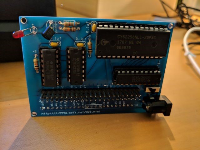
Powering the Board
The board has a switch that you can choose to power the board from the sideport 5V supply or an external 5V supply. The board has a DC 2.1x5.5mm power jack for supplying external power. I had such a supply on hand. The website for the board points out that the TI-99/4a speech synthesizer does not pass power on pin #1 (which is the 5V supply). So if you plug the 32k memory board into the speech synthesizer you have to use the external power supply. Or you can mod the speech synthesizer board to jumper the power across. I experimented with plugging the 32k expansion board directly to the side port and into the speech synthesizer.
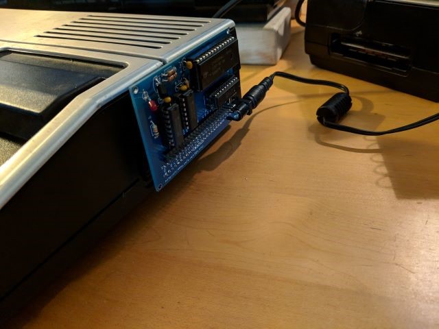
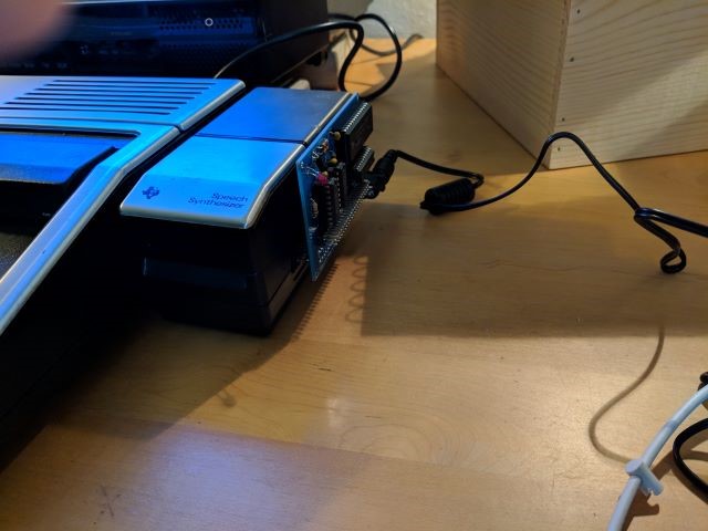
I learned a couple things from these experiments.
1) It is pretty hard to remove the 32k expansion board from the ti99-4a sideport.
It was much easier removing it from the side the the speech synthesizer.
2) When plugged directly into the TI, and using the TI supplied power, pin 1 of
the expansion port did not receive power.
For item 2 I took a look at the gerber files to see what was happening.
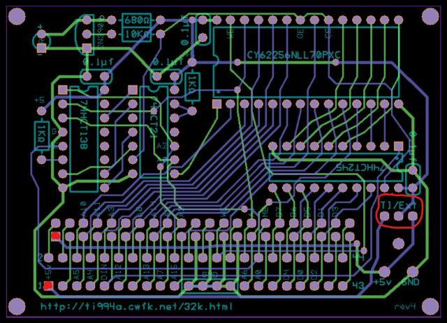
In the image above I circled the switch labeled “TI/EXT” that allows you to select the 5V source. If the switch is in the “TI” position the 5V comes from pin 1 of the TI header, which is the bottom most red square on the left. If the switch is in the “Ext” position the 5V from the power jack and powers the board and pin 1 of the expansion header, which is the upper red square on the left. So the expansion header 5V power can only come from the external power jack power. So if I want to use that power for my own board, the external power adapter is required.
How it works
As long as I was looking at the gerbers I decided to figure out how it works. The implementation looks very much like the Do-it-yourself card from the TI-99/4A Tech Pages.
Does it Work?
TI Extended Basic has a command SIZE that reports how much free memory there is. Without the 32K expansion card it reported
* READY *
>SIZE
   13928 bytes free
Plugging in the 32K expansion card it reported
* READY *
>SIZE
   13928 bytes of stack free
   24488 bytes of program space free
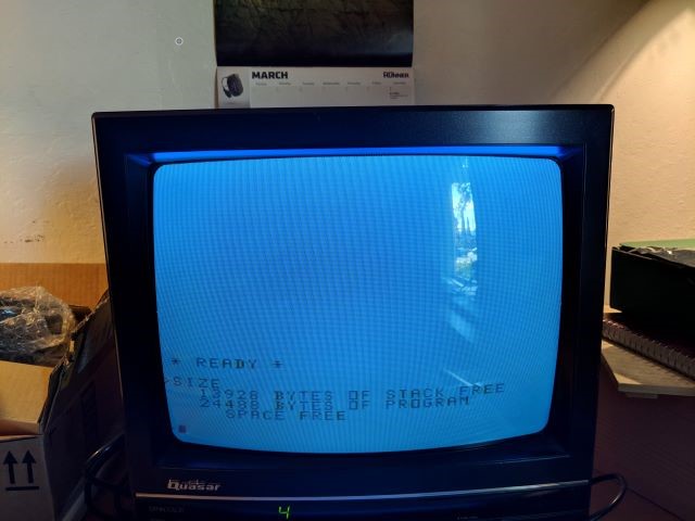
So, Yay! It appears to be working!
However, I was a little disappointed that I did not see the LED on the board light up. Looking at the gerbers I see that the LED is controlled by the SRAM CE signal. The CE signal is generated by the address decoding logic. So I wrote a little basic program to peek at the memory at 8192 (>2000) which is the lower memory expansion area. Here is the program
10 A=8192
20 CALL PEEK(A,X1,X2,X3,X4)
30 PRINT X1
40 A=A+8
50 GOTO 20
Running that program I saw the LED blink. Yay!
However the LED was very dim. I think the 680 Ohm resistor is limiting the current a little too much.